Sometimes it is necessary to save a Civil 3D 2012 file for another user that is running an older CAD version of AutoCAD. Civil 3D 2012 provides two menu items that both appear to be able to accomplish this however, they don't produce the same results. If you are in a 2012 drawing and select "Save As" "AutoCad Drawing" from the application menu, you'll see a pop up window where you will be able to select a file name and a file type. Saving a CAD file to an older version using this method will allow you to open the file in an older version of CAD but you may not have all of the Civil 3D 2012 settings available.
The first indication that this has happened is if you see this notice when opening a Civil 3D 2010 drawing.
"This drawing was created with a newer version of Civil 3D. All entities created by Civil 3D within the drawing are in a proxy state. Additionally, all commands, settings, and displays of Civil 3D are disabled for this drawing."
A better way to save a 2012 drawing to an older version is to use "Export" "AutoCAD DWG" from the application menu. From this menu select a version that matches or is closest to the one that will be used to open the CAD file. Using this method should preserve all or most of the commands, settings and displays from the newer version. Maybe the next release of Civil 3D will resolve some of these version compatibility issues.
Thanks,
William
Monday, April 9, 2012


Tuesday, April 3, 2012
Complimentary Civil 3D Training
Wed. April 11, 2012
12:00pm - 1:00pm CT
Sponsored by Eagle Point software
Eagle Point Software invites you to join us for a complimentary training class* on how to grade a site in AutoCAD Civil 3D.
Attend "Grading Groups" to learn:
• How to use feature lines and grading groups to create a proposed surface.
• How to create the proposed surface automatically and how that surface is dynamically linked to the grading group.
This in-depth look at grading groups provides information that is extremely helpful when designing
*This is a live, instructor-led class delivered via GoTo Meeting.
12:00pm - 1:00pm CT
Sponsored by Eagle Point software
Eagle Point Software invites you to join us for a complimentary training class* on how to grade a site in AutoCAD Civil 3D.
Attend "Grading Groups" to learn:
• How to use feature lines and grading groups to create a proposed surface.
• How to create the proposed surface automatically and how that surface is dynamically linked to the grading group.
This in-depth look at grading groups provides information that is extremely helpful when designing
*This is a live, instructor-led class delivered via GoTo Meeting.
Acronym Online
http://acronymonline.org/top-ways-government-utilizing-autocad-software/?elq=fe80d13ca13b43b484896f6f1117e2b7&elqCampaignId=90
Friday, February 10, 2012
New source for AutoCAD training
Global eTraining by Digital School offers training materials for AutoCAD and AutoCAD Civil 3D at reasonable prices. The courses are not instructor led but instead are a collection of training materials that when purchased are available to you online for an entire year to use at your own pace.
The options available are as follows....
Full Course Library $845 per user
Guided Option $525 per user
Flexible Option $395 per user
Certification Option $149 per user
Compare this to DC CADD which can cost up to $1000 per person for one 4 day instructor led course.
This might be a good alternative if training budgets are tight.
You can get more detail on what is offered with each option by following this link to the Global eTraining website.
http://www.globaletraining.ca/autocad/index.php
Thanks,
William
The options available are as follows....
Full Course Library $845 per user
Guided Option $525 per user
Flexible Option $395 per user
Certification Option $149 per user
Compare this to DC CADD which can cost up to $1000 per person for one 4 day instructor led course.
This might be a good alternative if training budgets are tight.
You can get more detail on what is offered with each option by following this link to the Global eTraining website.
http://www.globaletraining.ca/autocad/index.php
Thanks,
William
Monday, January 30, 2012
Autodesk Certification Day
On February 10th, 2012, Autodesk will be offering discounted certification exams for a select group of 2012 products. These include.....
• AutoCAD 2012
• AutoCAD Civil 3D 2012
• Autodesk 3ds Max Design 2012
• Autodesk Inventor 2012
• Autodesk Revit Architecture 2012
The normal cost for these certification exams is $75 for the Associate Exam and $125 for the Professional Exam. However on February 10th Autodesk will be offering these exams for a $25 registration fee and because SARA is a subscription customer you get $20 back.
That means each exam only costs you $5. This is a great deal if feel you are ready to take one of these exams.
The Associate exam is 60 minutes long and is multiple choice which requires a score of 77 to pass and obtain your certification.
The professional exam is a 90 minutes long hands-on exam using the Autodesk software and requires a passing score of 80. To obtain the Certified Professional certification you must pass both exams.
Upon successfully passing, both your name and certification number gets listed in the certified professional database and you receive a digital certificate and logo.
It's a great way to let your employer and others know that you possess the CAD skills that set you apart from the average user.
• AutoCAD 2012
• AutoCAD Civil 3D 2012
• Autodesk 3ds Max Design 2012
• Autodesk Inventor 2012
• Autodesk Revit Architecture 2012
The normal cost for these certification exams is $75 for the Associate Exam and $125 for the Professional Exam. However on February 10th Autodesk will be offering these exams for a $25 registration fee and because SARA is a subscription customer you get $20 back.
That means each exam only costs you $5. This is a great deal if feel you are ready to take one of these exams.
The Associate exam is 60 minutes long and is multiple choice which requires a score of 77 to pass and obtain your certification.
The professional exam is a 90 minutes long hands-on exam using the Autodesk software and requires a passing score of 80. To obtain the Certified Professional certification you must pass both exams.
Upon successfully passing, both your name and certification number gets listed in the certified professional database and you receive a digital certificate and logo.
It's a great way to let your employer and others know that you possess the CAD skills that set you apart from the average user.
Monday, September 19, 2011
Exporting to shapefile
Since our last upgrade to arcmap 10.0 took place I've started having problems exporting shapefiles from Autocad civil 3D 2010 and 2012 to ArcMap compatible files. Using "mapexport" in Civil 3d to export my polygons worked without any problems when sharing between Civil 3D 2010 and ArcMap 9.* but not with this newer version.
Trying to add your shapefile into ArcMap 10 will produce a window with the following message....
"Open Failed"
"Error opening feature class"
"Number of shapes does not match the number of table records"
The file should be repairable by using ArcCatalog however files with this type of error are not even accessable by ArcCatalog. The best solution I've found is to use a program called "shapecheck.exe" When running shapecheck you'll be asked for the path and name of the shapefile needing repair. After selecting the file follow the onscreen instrucitons to "Build SHX" then "Check DBF" and lastly selecting quit to exit the program.
Running my shape files through this program takes only a couple of seconds and results in useable shape files with no known issues or problems. At this point I am not sure if this is an isolated problem with my installation so I haven't made this repair program available on our server. If you are having this same problem with your shape files please contact me so I can provide you with a copy of shapecheck.exe
Thanks,
William
Trying to add your shapefile into ArcMap 10 will produce a window with the following message....
"Open Failed"
"Error opening feature class"
"Number of shapes does not match the number of table records"
The file should be repairable by using ArcCatalog however files with this type of error are not even accessable by ArcCatalog. The best solution I've found is to use a program called "shapecheck.exe" When running shapecheck you'll be asked for the path and name of the shapefile needing repair. After selecting the file follow the onscreen instrucitons to "Build SHX" then "Check DBF" and lastly selecting quit to exit the program.
Running my shape files through this program takes only a couple of seconds and results in useable shape files with no known issues or problems. At this point I am not sure if this is an isolated problem with my installation so I haven't made this repair program available on our server. If you are having this same problem with your shape files please contact me so I can provide you with a copy of shapecheck.exe
Thanks,
William
Friday, September 9, 2011
Civil 3D 2012 text hotfix
A new discovery in Civil 3D 2012 is text that cannot be modified. I experienced this the other day when trying to label and dimension a CAD drawing. The text was immune to all efforts to move, erase, rotate, etc. the text was somehow locked into it's current state. It would dissapear after executing the command but reappear after a regen. If you experience this problem I recommend using this hotfix to return the text to an editable state.
1. At the command prompt type DTEXTED. (This is the dtext editor mode selector.)
2. Type 1 & Press [ENTER]. (Setting the dtext editor mode 2 = new dynamic edit
in place mode & 1 = classic edit text in dialog box.)
3. Type AUDIT. Press Y to fix all errors. (Forces Civil 3d to stop locking items
& use new mode)
4. Save your drawing and now you will not have the problem with the locked out
text.(Object was open for read = error)
Dont forget to run the Audit command after changing the Dtext editor or the changes wont work.
Hope this helps.
1. At the command prompt type DTEXTED. (This is the dtext editor mode selector.)
2. Type 1 & Press [ENTER]. (Setting the dtext editor mode 2 = new dynamic edit
in place mode & 1 = classic edit text in dialog box.)
3. Type AUDIT. Press Y to fix all errors. (Forces Civil 3d to stop locking items
& use new mode)
4. Save your drawing and now you will not have the problem with the locked out
text.(Object was open for read = error)
Dont forget to run the Audit command after changing the Dtext editor or the changes wont work.
Hope this helps.
Wednesday, August 10, 2011
TIPniques: Why You Should Be Using Sheet Sets
Interesting article from the Autodesk User Group International (AUGI).
The article describe how using Sheet Sets in AutoCAD can improve efficiency,
simplify batch plotting and help with how users are creating and saving files.
http://www.augi.com/library/tipniques-why-you-should-be-using-sheet-sets/
The article describe how using Sheet Sets in AutoCAD can improve efficiency,
simplify batch plotting and help with how users are creating and saving files.
http://www.augi.com/library/tipniques-why-you-should-be-using-sheet-sets/
Wednesday, May 4, 2011
Problems with hatch patterns
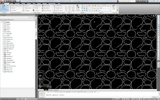
In some cases you may have encountered a situation where hatch patterns don’t turn out quite as expected.
Here’s a close up view of a gravel hatch pattern where the closed objects appear broken and jagged.
Recommended fix can be found at...
http://usa.autodesk.com/adsk/servlet/ps/dl/item?siteID=123112&id=10100419&linkID=9240617
Solution
To resolve this problem, change the origin of the hatch pattern. To do this, you can either move the hatch origin to the hatch boundary or specify a point to be used as the hatch origin.
To move the hatch origin to the hatch boundary
1. Double-click the affected hatch.
2. In the Hatch Edit dialog box, under Hatch Origin, verify that the Specified Hatch Origin option is selected.
3. Select the Default to Boundary Extents check box.
4. Click OK.
To specify a point to be used as the new hatch origin
1. Double-click the affected hatch.
2. In the Hatch Edit dialog box, under Hatch Origin, verify that the Specified Hatch Origin option is selected.
3. Click the Click to Set New Origin button.
4. Click a point that is closer to the hatched object.
5. Click OK.
Another option which I’ve found to work equally well is to select the affected hatch pattern or patterns then right click to obtain a popup menu. In that menu select “Set Origin” then click anywhere near your hatch pattern. Your hatch should automatically update. Give it a try.
Here’s a close up view of a gravel hatch pattern where the closed objects appear broken and jagged.

Recommended fix can be found at...
http://usa.autodesk.com/adsk/servlet/ps/dl/item?siteID=123112&id=10100419&linkID=9240617
Solution
To resolve this problem, change the origin of the hatch pattern. To do this, you can either move the hatch origin to the hatch boundary or specify a point to be used as the hatch origin.
To move the hatch origin to the hatch boundary
1. Double-click the affected hatch.
2. In the Hatch Edit dialog box, under Hatch Origin, verify that the Specified Hatch Origin option is selected.
3. Select the Default to Boundary Extents check box.
4. Click OK.
To specify a point to be used as the new hatch origin
1. Double-click the affected hatch.
2. In the Hatch Edit dialog box, under Hatch Origin, verify that the Specified Hatch Origin option is selected.
3. Click the Click to Set New Origin button.
4. Click a point that is closer to the hatched object.
5. Click OK.
Another option which I’ve found to work equally well is to select the affected hatch pattern or patterns then right click to obtain a popup menu. In that menu select “Set Origin” then click anywhere near your hatch pattern. Your hatch should automatically update. Give it a try.
Thursday, December 9, 2010
civil 3d 2010 raster images
Different options are available in civil 3d 2010 for working with raster images. Depending on your installation some may or may not work. Or, they may work but not quite as expected.
One way inserting images can be accomplished is by way of map space or “MAPWSPACE” data connection but that slows things down quite a bit.
Going down that path really stresses your computer resources and slows down your machine so I try to stay away from it. There are some specific instances for using
it, one being that you can combine drawings with different spatial references (Autodesk's claim not mine). But since we've adopted nad83 as our standard, it's rare that we should have the need to combine nad27 and nad83 data.
Also, the “insert” Icon on the image ribbon doesn’t work on some workstations. If I click on that icon I get an error message saying that “IINSERT” is an unknown command. The work around for this would involve re-installing autoCAD which i'm not up for at this time.
A quick survey of our cad users, myself included, indicates that the best method is to insert raster images by using the tool-based geospatial workspace (available on workspace switching tab in the lower right hand corner).
Selecting this option brings up new panel titles where you can select "Insert" then on the new ribbon that appears select the Image icon. However, some of us oldtimers that still prefer typing commands can just type in "mapiinsert" and we arrive at the same pop up window with less ribbons and tabs to click thru.
Pay close attention to the quality of your printed raster images also. Don't accept poor quality images, if it looks better on your screen than on paper, chances are you may need to look into your method for inserting images.
Thats it for now, thanks to Richard and Emilio for their input on this topic.
One way inserting images can be accomplished is by way of map space or “MAPWSPACE” data connection but that slows things down quite a bit.
Going down that path really stresses your computer resources and slows down your machine so I try to stay away from it. There are some specific instances for using
it, one being that you can combine drawings with different spatial references (Autodesk's claim not mine). But since we've adopted nad83 as our standard, it's rare that we should have the need to combine nad27 and nad83 data.
Also, the “insert” Icon on the image ribbon doesn’t work on some workstations. If I click on that icon I get an error message saying that “IINSERT” is an unknown command. The work around for this would involve re-installing autoCAD which i'm not up for at this time.
A quick survey of our cad users, myself included, indicates that the best method is to insert raster images by using the tool-based geospatial workspace (available on workspace switching tab in the lower right hand corner).
Selecting this option brings up new panel titles where you can select "Insert" then on the new ribbon that appears select the Image icon. However, some of us oldtimers that still prefer typing commands can just type in "mapiinsert" and we arrive at the same pop up window with less ribbons and tabs to click thru.
Pay close attention to the quality of your printed raster images also. Don't accept poor quality images, if it looks better on your screen than on paper, chances are you may need to look into your method for inserting images.
Thats it for now, thanks to Richard and Emilio for their input on this topic.
Monday, August 23, 2010
Thursday, April 22, 2010
Workspace problems
New problem discovered when trying to toggle image frames on and off.
Clicking on the Icon for toggling frames would produce this message....
C:\Program Files\AutoCAD Raster Design 2010\AeciUi51.arx cannot find a dll or
other file that it needs.
Unknown command "IFRAME". Press F1 for help.
If you switch your workspave to 2D Drafting and Annotation you'll get the same message whenever you try using any of the icons on that pallet. I forwarded a description of the problem to IT. They've been working with experts at DC CADD to help eliminate these bugs. I'll let everyone know if and when it gets resolved.
Hopefully everyone is getting used to using 3D 2010. I haven't completely stopped using 3D 2008 yet but probably only use it about 5% of the time.
William
Clicking on the Icon for toggling frames would produce this message....
C:\Program Files\AutoCAD Raster Design 2010\AeciUi51.arx cannot find a dll or
other file that it needs.
Unknown command "IFRAME". Press F1 for help.
If you switch your workspave to 2D Drafting and Annotation you'll get the same message whenever you try using any of the icons on that pallet. I forwarded a description of the problem to IT. They've been working with experts at DC CADD to help eliminate these bugs. I'll let everyone know if and when it gets resolved.
Hopefully everyone is getting used to using 3D 2010. I haven't completely stopped using 3D 2008 yet but probably only use it about 5% of the time.
William
Friday, April 9, 2010
Exporting shape files from Civil3D 2010
Latest problem related to civil 3D 2010 is that of exporting data from Autocad to shape files. If you haven't had a need to create shape files yet and haven't seen the problem first hand, you can visit this website for a description of it.
http://blog.121pcs.com/mapexport-to-shp-creates-empty-file-in-civil-3d-2010.html
Trying the recommended fix was unsuccessful so I had to contact our IT department for help. They recommended the following solution which fixed the problem.
"Here is the fix – I put the file here: \\guentherdata\disk2disk\appl-2\acad\2010\Install shortcuts\Patches
Take the mapexport.ini file that is there and copy it to: c: \Documents and Settings\All Users\Application Data\Autodesk\C3D 2010"
If your mapexport.ini file already exists, overwrite it with this new one. So far everyone has had success with this repair.
William
http://blog.121pcs.com/mapexport-to-shp-creates-empty-file-in-civil-3d-2010.html
Trying the recommended fix was unsuccessful so I had to contact our IT department for help. They recommended the following solution which fixed the problem.
"Here is the fix – I put the file here: \\guentherdata\disk2disk\appl-2\acad\2010\Install shortcuts\Patches
Take the mapexport.ini file that is there and copy it to: c: \Documents and Settings\All Users\Application Data\Autodesk\C3D 2010"
If your mapexport.ini file already exists, overwrite it with this new one. So far everyone has had success with this repair.
William
Wednesday, March 31, 2010
Inserting excel files into AutoCAD
Here's a handy set of insctrucions that really came in handy the other day. I was struggling to insert an excel spreadsheet into autocad as an ole object. I wanted to be able to view and print the spreadsheet along with the rest of the information in my drawing. I also wanted to retain the link to the excel file so that any updates to it would automatically update in my cad file. Civil3D 2010 wasn't cooperating and I was getting unexpected unsatisfactory results. Fortunately I came across this set of instructions from "CAD Geek". Instructions were written for Civil3D 2008 but will also work in 2010 version. Here's a link to the article, not sure how long it will be up on the site though so you might want to cut and paste it into a word file for safe keeping.
http://www.thecadgeek.com/blog/2007/04/13/linking-excel-and-autocad-with-data-links/
William
http://www.thecadgeek.com/blog/2007/04/13/linking-excel-and-autocad-with-data-links/
William
Wednesday, March 24, 2010
Civil 3D layer "0"
Recently I've begun to experience some problems with layer visibility in AutoCAD 2010. Trying to find the correct layer to freeze in a viewport or freezing layers in xrefs has been a real headache. I never seem to get the results I want or expect. I tracked the problem to entities being drawn on layer 0 and did more research on the web and various softdesk resources. It seems to be a common problem mainly because 2010 relies heavily on styles. The recommended solution.....Reserve layer 0 for insertion of blocks and xrefs only. Don't draw anything in this layer. Every line, polyline, circle, arc, text, etc... needs to on a layer other than 0. I was trying to avoid posting a long, wordy explanation of this, so if you need more info just let me know.
Thanks,
William
Thanks,
William
Thursday, March 18, 2010
Civil 3D 2010 ctb files
Back when Autocad Civil 3D 2008 was our only CAD application, we learned that Autocad stores all ctb files on folders located on our computer C: drives. Problem with this was that if we were part of a group working on a project the only way we could share ctb plot style tables was to e-mail them to each other or place a copy on the network that we could then copy into our C: drive. After a while we also learned that if we placed all of our ctb files in one central location on a network drive and redefined our search path in Autocad we could all have access to the latest project ctb files.
Now that we are all hopefully using Civil 3D 2010 we need to be sure and make the same adjustments to our ctb file search path. Here is a reminder on how to do this.
Open up Autocad Civil 3D 2010 and type in "options" at the command prompt. In the Options pop up window click on the Files tab. In the list of "Search paths, file names, and locations", expand the "Printer File Support File Path" item. On that list expand the "Plot Style Table Search Path" item. Once there you should see the path and name to the default folder that Civil 3D is using to search for ctb files. Click this path to select it then click on "Remove" to remove it.
You'll be left with an empty box where you can type in the new search path. In this box type in, W:\dwgs-1\projectCTBfiles. Click "add", "Apply" and "OK". That's it, you should now see all ctb files that we have saved in that folder. If you create any new ones that need to be shared with others on a project remember to save them to this location.
Thanks,
William
Now that we are all hopefully using Civil 3D 2010 we need to be sure and make the same adjustments to our ctb file search path. Here is a reminder on how to do this.
Open up Autocad Civil 3D 2010 and type in "options" at the command prompt. In the Options pop up window click on the Files tab. In the list of "Search paths, file names, and locations", expand the "Printer File Support File Path" item. On that list expand the "Plot Style Table Search Path" item. Once there you should see the path and name to the default folder that Civil 3D is using to search for ctb files. Click this path to select it then click on "Remove" to remove it.
You'll be left with an empty box where you can type in the new search path. In this box type in, W:\dwgs-1\projectCTBfiles. Click "add", "Apply" and "OK". That's it, you should now see all ctb files that we have saved in that folder. If you create any new ones that need to be shared with others on a project remember to save them to this location.
Thanks,
William
Wednesday, March 17, 2010
Recent developments
Last week I attempted to develop a list of steps required to prepare roadway plan and profiles. If anyone has ever tried doing this I'm sure you've realized that you can soon get lost traveling through a maze of Civil3D help topics. Starting with one topic which then leads to another and another. You soon forget what you were trying to research in the first place. My goal was to work through all of the civil3d instructions and help menus then compile them and simplify them into one word document that would hopefully be easier to understand. Things were progressing well until I reached the point where I was attempting to create section views at various stations along the roadway. In order to do this you first need to create a corrridor. No problem except that upon trying to do so, I discovered that all of the corridor model tool palettes were missing. Time do to some investigating. Using the internet I soon figured out that others were having the same problem, this eventually led me to this autodesk website.
http://usa.autodesk.com/adsk/servlet/ps/item?siteID=123112&id=13326059&linkID=9240697
Sounds like an IT issue to me. I forwarded the problem and the recommended solution to our friends in IT department who promised to re-install Civil 3D sometime next week. At that point I'll complete the Roadway plan/profile and cross section instructions and get them out to everyone to tryout and critique.
William
http://usa.autodesk.com/adsk/servlet/ps/item?siteID=123112&id=13326059&linkID=9240697
Sounds like an IT issue to me. I forwarded the problem and the recommended solution to our friends in IT department who promised to re-install Civil 3D sometime next week. At that point I'll complete the Roadway plan/profile and cross section instructions and get them out to everyone to tryout and critique.
William
Subscribe to:
Posts (Atom)
